Drone Frame
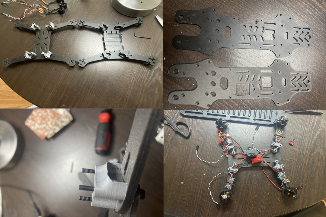
The original 3D printed PLA material used for the frame was a concern. Even before flight testing or testing the motors attached to the leg frame it felt a bit weak. As well as having to take into account if during flight if the material can handle all for motors as well as the tension created from that. Also, if the frame takes significant contact, it will likely shatter.
The solution to this was rather simple as I began exploring different materials I could buy or have access to on campus. This led me to the path of looking into the ITL (Integrated Teaching and Learning Lab), which had access to the Onyx print mater from the MarkForged Printer. Compared to PLA Onyx is a professional-grade material designed for high strength, stiffness, and heat resistance material. Due to the Nylon being reinforced with Carbon Fiber, which is also important for stiffness and rigidity when flying.
Another adjustment I had to make due to feedback and personal opinion was making the center section between my base plate and cover bigger. I just made the ESC cable spacers a quarter of an inch taller in Fusion. This allowed for more clearance room in the compartment for my power and ground solder joints, UBEC 5v regulator and my FlySky FS-iA6Breceiver. As well as increasing spaces on my plate cover for cable management specifically for my flight controller. (Pictures Right)
Control System
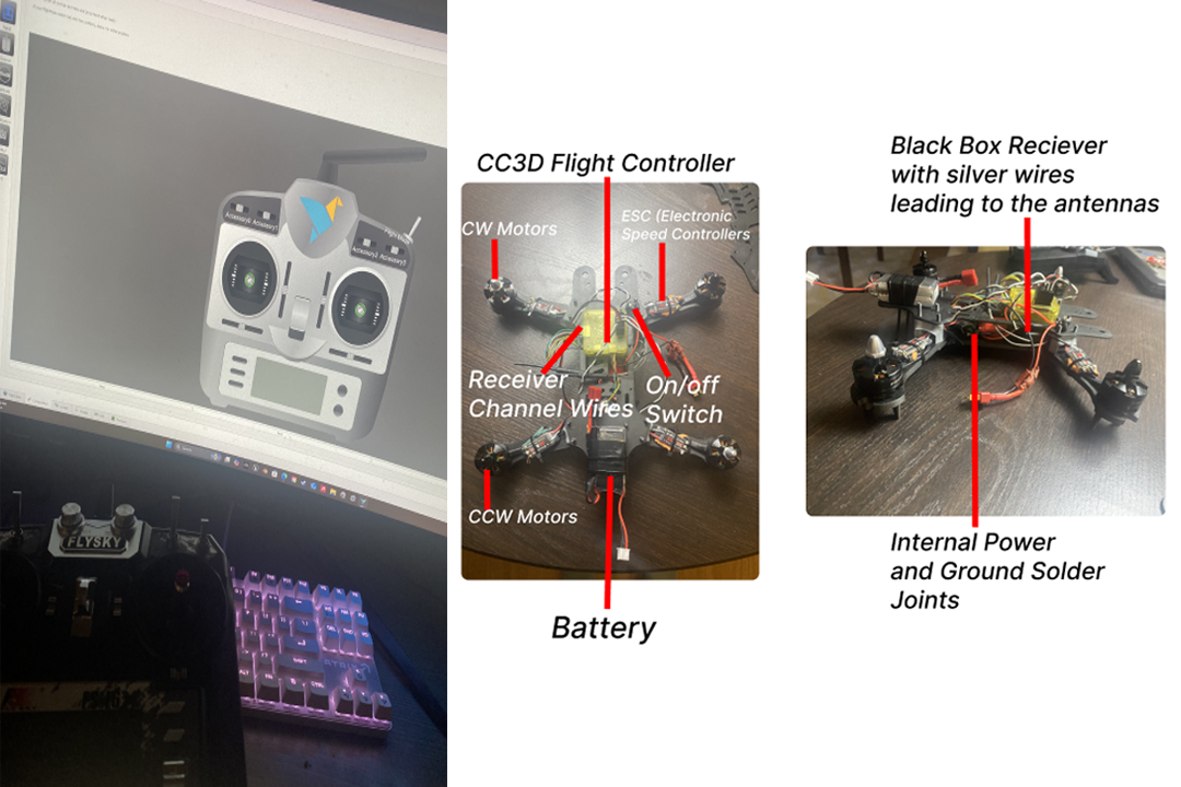
So, for my control system I ended up using the CC3D flight controller which is a 32-bit processor, 3-axis gyroscope, and 3-axis accelerometer. The CC3D relies upon the library and software called LibrePilot. The next step was to attach the female ESC headers onto the appropriate header on the CC3D. Through the LibrPilot platform I began Motor testing and calibration. This was done through keyboard inputs and the software, which confirmed my wiring was correct and my Motors where fully fictional through my CC3D.
Transmitter/Receiver
I began connecting individual receiver channel signal wires to individual input headers on the flight controller for a PWM signal. When beginning the transmitter input calibration after testing again I was getting joystick responses on the software. Using the LibrePilot software I saved those calibrations on my profile for the FlySky FS-T6 transmitter/controller I’m using.
The final step before moving onto flight testing was doing motor response testing from my FlySky FS-T6 inputs. The drone was not connected to my USB, and I tested it off just using the drone's battery Tattu 800mAh 7.4V 45C 2S1P LiPo Battery. The drone powers on using a power switch I soldered and installed and everything successfully powers on, including the receiver which gets power from my flight controller.
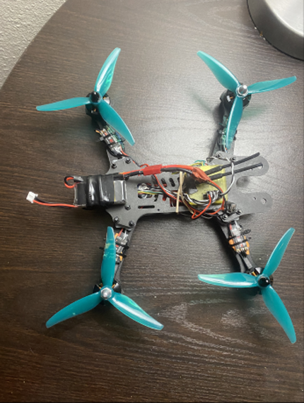
My input holding my left joystick to throttle was successful in powering on all the motors. Of course with propellers not installed, my controller inputs were responsive when using my roll and pitch joystick as you saw individual motors slow down or speed up. (Pictures on Left)
Final Build
Testing Videos